
Background
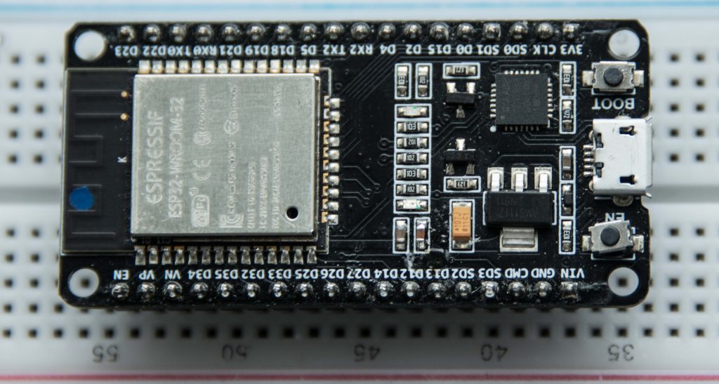
I recently had a need to send signals from a Raspberry Pi to an ESP32 (a brilliant little product, which costs around £5 and provides dual core CPU, WiFi, Bluetooth and programmable GPIO pins.) using the GPIO pins on both devices.
The actual requirement was to determine if the ESP32 could be used as a low cost device to receive a signal on its GPIO pins from a detector, and transmit an ackowledgement of that signal over WiFi. The detector we were looking to connect to the ESP32 was a neutron detector, which apart from being rather expensive and sensitive, does require a source of neutrons to detect, which makes experimenting and testing challenging.
What we needed to determine was:
- What was the fastest frequency that ESP32 could reliably detect? (i.e What was the minimum time between Pin High : Pin Low events that the ESP32 would respond to?)
- What rate of incoming signals of this frequency could the ESP32 reliably respond to?
I put together a P.o.C. comprising of:
- A Raspberry Pi C program to switch a GPIO pin to High : Low with an optional delay between each signal
- An ESP32 program to listen for the incoming siganls and trasmit a count of the signals over WiFi
- A C# program to connect, via sockets, to a given IP address and take incoming data.
The P.o.C. was a little more complex than the three word header might suggest.
Raspberry Pi C program to switch a GPIO
//
//  How to access GPIO registers from C-code on the Raspberry-Pi
//  Example program
//  15-January-2012
//  Dom and Gert
//  Revised: 15-Feb-2013


// Access from ARM Running Linux

#define BCM2708_PERI_BASE        0x3F000000
#define GPIO_BASE                (BCM2708_PERI_BASE + 0x200000) /* GPIO controller */


#include <stdio.h>
#include <stdlib.h>
#include <fcntl.h>
#include <sys/mman.h>
#include <unistd.h>
#include <time.h>

#define PAGE_SIZE (4*1024)
#define BLOCK_SIZE (4*1024)

int  mem_fd;
void *gpio_map;

// I/O access
volatile unsigned *gpio;

// GPIO setup macros. Always use INP_GPIO(x) before using OUT_GPIO(x) or SET_GPIO_ALT(x,y)
#define INP_GPIO(g) *(gpio+((g)/10)) &= ~(7<<(((g)%10)*3))
#define OUT_GPIO(g) *(gpio+((g)/10)) |=  (1<<(((g)%10)*3))
#define SET_GPIO_ALT(g,a) *(gpio+(((g)/10))) |= (((a)<=3?(a)+4:(a)==4?3:2)<<(((g)%10)*3))

#define GPIO_SET *(gpio+7)  // sets   bits which are 1 ignores bits which are 0
#define GPIO_CLR *(gpio+10) // clears bits which are 1 ignores bits which are 0

#define GET_GPIO(g) (*(gpio+13)&(1<<g)) // 0 if LOW, (1<<g) if HIGH

#define GPIO_PULL *(gpio+37) // Pull up/pull down
#define GPIO_PULLCLK0 *(gpio+38) // Pull up/pull down clock
#define PIN 4
#define MONITOR 100000

void setup_io();

int main(int argc, char **argv)
{
  int g,rep;
  struct timespec gettime_start;
  struct timespec gettime_now;
  long int time_diff_secs, time_diff_nano;
  int sleep = 250;

  // Set up gpi pointer for direct register access
  setup_io();

  // Switch GPIO 7 to output mode

 /************************************************************************\
  * You are about to change the GPIO settings of your computer.          *
  * Mess this up and it will stop working!                               *
  * It might be a good idea to 'sync' before running this program        *
  * so at least you still have your code changes written to the SD-card! *
 \************************************************************************/

  INP_GPIO(PIN); // must use INP_GPIO before we can use OUT_GPIO
  OUT_GPIO(PIN);

  printf("Pin %d set to output v2.4\n", PIN);

  rep =0;
  g = 0;
  clock_gettime(CLOCK_REALTIME, &gettime_start);

  while(1)
  {
    GPIO_SET= 1 << PIN;
    //usleep(1);
    GPIO_CLR = 1<< PIN;
    rep++;
    g++;

    if (g >= MONITOR)
    {
        clock_gettime(CLOCK_REALTIME, &gettime_now);
        time_diff_secs = gettime_now.tv_sec - gettime_start.tv_sec;
        time_diff_nano = gettime_now.tv_nsec - gettime_start.tv_nsec;
        gettime_start = gettime_now;

        if (time_diff_nano< 0)
        {
            time_diff_nano += 1000000000;
            time_diff_secs--;
        }

        printf("Sent %d signals with delay of %d uSecs in %ld Secs %ld nSecs \n", g, sleep, time_diff_secs, time_diff_nano );
        g = 0;
    }
    usleep(sleep);
  }
  return 0;
} // main


//
// Set up a memory regions to access GPIO
//
void setup_io()
{
   /* open /dev/mem */
   if ((mem_fd = open("/dev/mem", O_RDWR|O_SYNC) ) < 0) {
      printf("can't open /dev/mem \n");
      exit(-1);
   }

   /* mmap GPIO */
   gpio_map = mmap(
      NULL,             //Any adddress in our space will do
      BLOCK_SIZE,       //Map length
      PROT_READ|PROT_WRITE,// Enable reading & writting to mapped memory
      MAP_SHARED,       //Shared with other processes
      mem_fd,           //File to map
      GPIO_BASE         //Offset to GPIO peripheral
   );

   close(mem_fd); //No need to keep mem_fd open after mmap

   if (gpio_map == MAP_FAILED) {
      printf("mmap error %d\n", (int)gpio_map);//errno also set!
      exit(-1);
   }

   // Always use volatile pointer!
   gpio = (volatile unsigned *)gpio_map;
printf ("Setup complete\n");

} // setup_io
The above was based on example code to program the GPIO pins by Dom and Gert, Jan 2012
The above C program basically executes a continuous loop that:
- sets GPIO pin 7 High
- optionally waits for n uSecs. (uSleep line commented out in example, so no delay.)
- sets GPIO pin 7 Low
- calls uSleep to wait for n uSecs (In the above example 250 uSecs)
The code also monitors the time the above operations take to execute MONITOR cycles. (In the example MONITOR is set to 100000)
The advantage of the above as a P.o.C, is that it is relatively easy obtain an idea of the frequency of each pulse (High : Low pair) and also to set how many pulses/sec are being initiated.
The frequency measured will not be the frequency of the pulse. What is being measured is the time taken to execute a Pin_High call and then a Pin_Low call, not the frequency of the pulse itself. However this figure will give a reasonably accurate ball-park value, and we do know that the pulse frequency itself will be faster than that obtained by the measurements, so there is merit in the figures.
Notice the calculation to determine the time taken for MONITOR pulses to be sent. When using the usleep function, the time is returned in a structure comprising of
- Seconds
- NanoSeconds.
To calculate a time span, we do the usual of subtracting a start time from and end time. However when subtracting the nanoSeconds arm, we have to be mindful that this can be negative. If it is then we simply add 1 second to the nanoSeconds arm (1000000000 in nanoSeconds) , and subtract one from the Seconds arm.
I highlight this because in a number of example uses of usleep I have seen published on the internet, the need to add 1,000,000,000 if the difference in the number of nanoSeconds is negative is documented as being caused by overflow. It isn’t. It is a consequence of the time being presented as whole seconds and fractions of a second.
Consider an end time of 5 seconds 200,000,000 nanoSeconds and a start time of 3 seconds and 500,000,000 nanoSeconds. The time difference between these is 1 second and 700,000,000 nanoSeconds. The result from a TimeSpan calculation though will return a result of 2 seconds and -300,000,000 nanoSeconds.
ESP32
Two main features that we needed to exploit on the ESP32 were:
- Dual Core
- WiFi
Dual Core
Whlst we didn’t , at this time, know the exact frequency of a pulse from the neutron detector, we did know that it would likely be in the range 1 uSec to 1 mSec. A core requirement was that all pulses are detected. We therefore could allow the detection of the pulses on the ESP32 to be interrupted by any other processes. We especially could not risk the Pulse detection code being disrupted by transmission of detection data.
To avoid this, we utilised the Dual Core feature of the ESP 32, and set about programming the Pulse detection on Core 0, and Data collation and transmission on Core 1.
Programming ESP32 – IDEs
Programming the ESP32 is a case of:
- Write code on a PC to which the ESP32 is connected (via USB)
- Compiling the Code to ESP32 assembly
- Flashing (i.e sending) the code to the ESP32.
There a number of enviroments available to assist in executing these steps:
- Espressif Command Line IDE
- Arduino IDE
- Eclipse (I believe, but have not used this)
- PlatformIO IDE which utilises Visual Studio
 Espressif IDE
Espressif provides a set of terminal/command line tools to perform the steps 2 & 3, together with a comprehensive set of liraries to assist in writing programs for the device (Including a version of FreeRTOS – a Runtime O/S).
Whilst the Espressif IDE does, in my opinion, provide the more comprehensive set of libraries and examples (not surprising as it is expressly for the Espressif set of SoCs), it is also the least friendly of the IDEs and the most likely to hit environmental issue that prevent it working.
 Arduino IDE
Probably the most straightforward enviroment for programming the ESP32 is to use the Arduino IDE. It is a lightweight UI based IDE, but powerful enough for the kinds of C/C++ development required for SoC programming. Plus, if you have an experience of SoC programming, then the chances are you already have experience of the Arduino IDE or one of its contempories.
It also comes loaded with a number of examples covering a range of libraries.
The down-side to the Arduino IDE is that the libraries are usually ports of libraries from other devices and so not necessarily tuned for the ESP32. As an example, using FreeRTOS, the minimum time you can delay a task is 1mSec, whereas on Espressif version it is 100uSecs. Which means using the Ardunio IDE you could switch a GPIO pin at a maximum frequency of 500Hz, with the Espressif IDE that maximum is raised to 5KHz.
PlatformIO
On the face of it, this appears to be the most sophisticated of the SoC IDE, and a really active community. The problem is I haven’t yet got it to work, at least on Windows 10 with the ESP32.